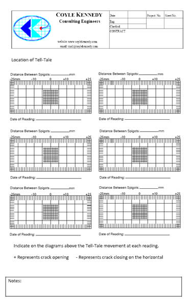
Structural Crack Monitoring
Home Coal Steam Turbine Blade Reverse Engineering, Upgrade, and Structural Design Steam Turbine Blade Reverse Engineering, Upgrade, and Structural Design. Keep your aircraft in the air with efficient structural integrity monitoring and realtime crack detection technology. Fast, cost effective fatique testing. Structural integrity and failure is an aspect of engineering which deals with the ability of a structure to support a designed load weight, force, etc. Chapter V. FLIGHT. It is a quiet evening in the steppe. The red disk of the sun has already touched the faraway, misty horizon. Its too late to get back. Download Ship. BuildingCADCAMCAECastingEDA Optical Softwaretutorials,training. ANSYS ansys Space. Claim 2. 01. 7. 2 Design. How to Evaluate Cracks in Poured Concrete Slabs, types of cracks in different types of structures, what causes them, what they mean, what repairs are needed. Ranger Hope version 2008, contains edits of material courtesy of Col Tritton A. N. T. A. publications. Vessel Structure. Design And Construction. Burn barrier mastic no. Spark Mechanical 2. Siemens SiemensLMSTestLab1. Figure 2. Comparison of tension, compression and flexure strength of DFC HexMC and quasi isotropic laminate ma de from the same prepreg batch. Nondestructive testing or nondestructive testing NDT is a wide group of analysis techniques used in science and technology industry to evaluate the properties of a. A. Math Statistics SAS JMP 1. RoadsBridges Sierrasoft geomatic 2. SchlumbergerTechlog2. House-Crack-Monitoring-Kit-672x372.jpg' alt='Structural Crack Monitoring' title='Structural Crack Monitoring' />Structural Analysis OASYS. Suite. 1. 4. 1. Cadence Cadence INCISIVE 1. Cadence Cadence GENUS 1. Cadence Cadence CONFRML 1. Autodesk Autodesk Power. Inspect 2. 01. 8. Update. BENTLEY Bentley Substation V8i0. Other CADCAM Gibbs. CAM 2. 01. 6 v. 11. DesignTools Auto. TURN for Autodesk Revit 2. BENTLEY LEAP Bridge Steel CONNECT Edition v. Structural Analysis CSI. SAP2. 00. 0. v. 19. Win. 64. petroleum IHS Kingdom Suite Advanced 2. Other CFD Dassault Systemes SIMULIA Simpack 2. Siemens Siemens. Tecnomatix. Plant. Simulation. Autodesk Autodesk Art. CAM 2. 01. 8. 1 Update. MENTOR Mentor Graphics Xpedition Enterprise VX. Geographic Information Schlumberger ECLIPSE 2. ANSYS ANSYS Electronics 1. Suite. Solid. Works Solid. Works 2. 01. 7 SP4. Full Premium Multilanguage. Other CADCAM ANSYS Products 1. Win. 64. Other CADCAM Mastercam 2. Update. 1 v. 20. 0. Virtual Reality Ventuz Technology Ventuz 5. R1. 85. 28. Development Csimsoft Bolt 2. Structural Analysis ARCHLine. XP 2. 01. 7 v. 17. Geographic Information Aquaveo Groundwater Modeling System Premium v. Optics Optiwave Opti. BPM 1. 2. Optics vpi transmission maker 9. Optics AGi. 32 v. Biomedicine Materialise Magics 2. Cadence Cadence Allegro and Or. CAD 1. 7. 2. 0. 0. Update. Siemens Siemens. Tecnomatix. CAD. Translators. Structural Analysis Tekla Structures v. SP3. BENTLEY MAXSURF CONNECT Edition v. BENTLEY Bentley. STAAD. Pro. Connect. Edition. BENTLEY Bentley SACS CONNECT Edition v. BENTLEY Bentley MOSES CONNECT Edition v. Other EDA Altium Designer 1. Other CADCAM Megatech Mega. CAD Metall 3. D 2. Other CADCAM Cad. Line Kft ARCHLine XP 2. Other CFD csimsoft Trelis Pro v. DesignTools Analdeta. Tessera. Pro. v. 3. BENTLEY Bentley RAM Elements CONNECT Edition v. BENTLEY Bentley RAM Connection CONNECT Edition v. ANSYS ANSYS opti. SLang 6. 1. 0. 4. Autodesk Autodesk Power. Mill 2. 01. 8. 0. Update. Optics LUCIDSHAPE 2. Other CADCAM OPEN MIND HYPERMILL 2. NI NI Multisim Component Evaluator 1. Other CFD ETA. Inventium. Pre. Sys. 2. 01. 7. R1. Win. 64. Other EDA Schneider Electric Sim. Sci Dynsim v. 5. 3. Other CFD artemis modal pro V5. Other EDA EPLAN Electric P8 v. Siemens Siemens Solid Edge ST1. PTC PTC. Creo. 3. M1. 40. petroleum Schlumberger. PIPESIM. 2. 01. 7. Other CADCAM Proge. SOFT proge. CAD 2. Pro v. 18. 0. 2. 3. ANSYS ANSYS 1. 8. Win. 64 Update Only. Other CADCAM solid. Thinking Clic. 2Form 2. Other CADCAM sheetworks V1. Other CADCAM Amada ap. Other CADCAM Metalix cnc. Kad v. 16. 4. 3. 25. MENTOR Mentor Graphics Xpedition Enterprise VX. Other CADCAM CIMCO Edit 8. Solid. Works Solid. Works 2. 01. 7 SP4 Full Premium. Other EDA Optenni Lab v. Other EDA Remcom XGTD v. Other EDA Remcom Wireless In. Site 2. 6. Other EDA TICRA CHAMP 3. Geological Prospecting Leica Cyclone 9. Other EDA Mician uwave Wizard 8. Siemens Siemens. NX. Easy. Fill. Advanced. Schlumberger. OLGA. IHS QUETOR 2. 01. Q3. Geographic Information Midland Valley Move v. Development Topcon. Magnet. Office. Tools. Structural Analysis Dlubal. PLATE BUCKLING. v. Structural Analysis Dlubal SHAPE MASSIVE 6. Other CADCAM Inventor. CAM 2. 01. 7. BENTLEY Bentley RM Bridge Advanced CONNECT Edition v. Development Topcon. Magnet. Field. PC. MSC MSC. ADAMS. v. MSC MSC sc. FLOw v. MSC MSC. Cradle. STREAM 1. MSC MSC Apex Grizzly 2. Treasure Hunt Games. Solid. Works FTI Blank. Works 2. 01. 6. 0. Other CADCAM Auto. Form Plus R7. 0. 3 Update. Autodesk Inventor. CAM 2. 01. 6 SP3 HF2 Multilang for Autodesk Inventor. Other CADCAM IMSPost 8. Suite Win. 64. Contact crackcadgmail. Steam Turbine Blade Reverse Engineering, Upgrade, and Structural Design. Steam turbine blade cracking often suggests the need for an upgraded blade design. Follow the process of reversing engineering a failed blade to produce a more reliable and efficient design. Blade reverse engineering is widely recognized as a crucial step in the product design cycle. Blade surface reconstruction is an iterative process to develop mathematical models from existing physical objects for finite element analysis FEA, computational fluid dynamics, and rapid prototyping in order to reduce product design lead time. In this process, precise data point measurement is important to create a valid shape. Due to the complexity of blade shape, the resultant model geometry change can lead to a large alteration in turbine performance see sidebar. Therefore, blade shape control is critical in the design process. In essence, the blade is a complex cantilever beam, and generating an accurate simulation result makes turbine blade analysis challenging. Finite element analysis is the accepted tool for turbine blade structural analysis. Both the model development upgrades and analysis will be discussed. Turbine Blade Design Fundamentals. Turbine blade design involves blade solid model development, thermo aerodynamics, and structural mechanics disciplines. The process of reverse engineering begins with determining the function of the machine part referred to as capturing design intent. The accuracy of reverse engineering is limited by the applied measurement and computer aided modeling techniques. A few of the major limitations are wear of the part numerical, sensing, and approximation errors and manufacturing methods. In order to ensure and enhance blade efficiency, optimizing the shape design of rotating and stationary blades is essential. The necessary steps for turbine blade reverse engineering are similar to those used in a new product development practice Figure 1. The process for steam turbine blade design from concept to actual product is an iterative one that includes computer aided design CAD models, including blade surface for computer aided manufacturing, FEAand, if necessary, computational fluidized dynamics reliability performance analysis and design modification. The following case study presents an industrial application of an integrated reverse engineering approach to turbine blade design. The study describes a developed engineering approach to designing and upgrading a steam turbine blade from an existing part. Data Point, Surface, and Cross Section Generation. Turbine blades present challenges to manufacturers to produce and maintain the blades complex free form surfaces and seemingly convoluted shapes. Contact measuring devices cannot gather enough data points to create an accurate surface profile of the airfoils irregular shape. Laser scanning is the best measurement method to capture the turbine blades entire complex features. After scanning the blade from multiple perspectives, the points of cloud data are rotated into the same reference frame and assembled into an exact 3. D model of the scanned part. The data points for this case study were edited using Geomagic Studio software. Following that, the blades entire 3 D surface was generated in the same environment. A perfect CAD model is necessary for machining and FEA because turbine blades must be highly consistent in shape, weight, and geometry in order to avoid vibration and other performance impeding characteristics. The entire CAD model can be compared with the original part to ensure the models quality. The inspection for this case study was performed with Geomagic Qualify engineering software. Inspection of the model and the original part indicated very good agreement 0. Tenon Inspection, Analysis, and Installation. Quality inspection of the turbine shaft assembly extends to the wheel steeple and the blade in order to collect information about the parts structural integrity and to draw a conclusion about the repair process, which can include actual repair or redesign. In this case, nondestructive testing NDT of the blades tenon revealed that a crack had initiated at the root of the tenon radius area Figure 2. The crack in the area of the tenon root at the base of the existing blade probably was caused by an improper size root radius, which could initiate cracking after the riveting process. The cracks appear to propagate after every cycle of the turbine operation sequence. Analysis was needed to determine the crack initiation mechanism at the root of the tenon. A 2 D FEA indicated a distortion at the tenon root radius area after peening, as shown in Figure 3. Peening the tenon involves deliberate plastic deformation, making it easy to understand the importance of high ductility in the blade material. Low ductility may create serious problems during the peening process, including cracks and even fractures in the tenons. The most critical process is riveting the tenon to deform it into the classic river shape as part of the shroud attachment process without this step, the tenon could not be attached. Clearly, correct assembly of the shroud band segments and riveting of the tenons are critical to long term reliability. The accepted refurbishment technique for blade tenon assembly is to reattach or resecure the cover band. Weld repair for blades where the crack was detected is one technique that was applied for purposes of this case study. Additional use of under cover band brazing further increased security of the attachment. Shaft Steeple Inspection and Redesign. NDT of the steeple revealed that a crack initiated at the root of the steeple hooks radius areas and appeared in every hook. In order to modify the stress field at the cracked area of the steeple hooks, a fir tree steeple configuration was proposed at the joint between the turbine blade and the disk. This joint represents the most critical load path within that assembly. A fir tree hook blade configuration has been commonly implemented in turbines because this design can accommodate multiple areas of contact over large contact loads. Figure 5 displays the proposed fir tree blade steeple configuration as a possible repair solution. The new blade base design is shown in Figure 6. Design of the fir tree geometry was carried out using a commercially available CAD package. The model was defined parametrically in order to incorporate changes throughout the design optimization process. Every step of the modeling process was checked to make sure an adequate geometry could be produced otherwise, a geometry failure was a signal to the optimizer to cancel or modify the model and the analysis. The blade root and the disk steeple geometry were defined in the same way as the basic tooth, with further parameters and rules needed. Because the fir tree steeple cross sectional geometry is constant along the root center line, it is possible to assume that stress is present in two dimensions, although the load is actually in three dimensions. Nonetheless, it is still possible to assume that each section behaves essentially as a 2 D axial symmetric problem with different loading applied on the hooks. In order to verify the feasibility of the fir tree configuration, comprehensive 2 D axial symmetric steeple and 3 D blade FEAs were executed on the original and the updated fir tree region of the blade disk assembly.